01
Application-engineered

Feeding · orientation · inspection · presentation
Custom component feeders and automated small-parts feeding systems built around your part, required orientation, sustained rate and the exact hand-off to your machine.
A reliable feed path
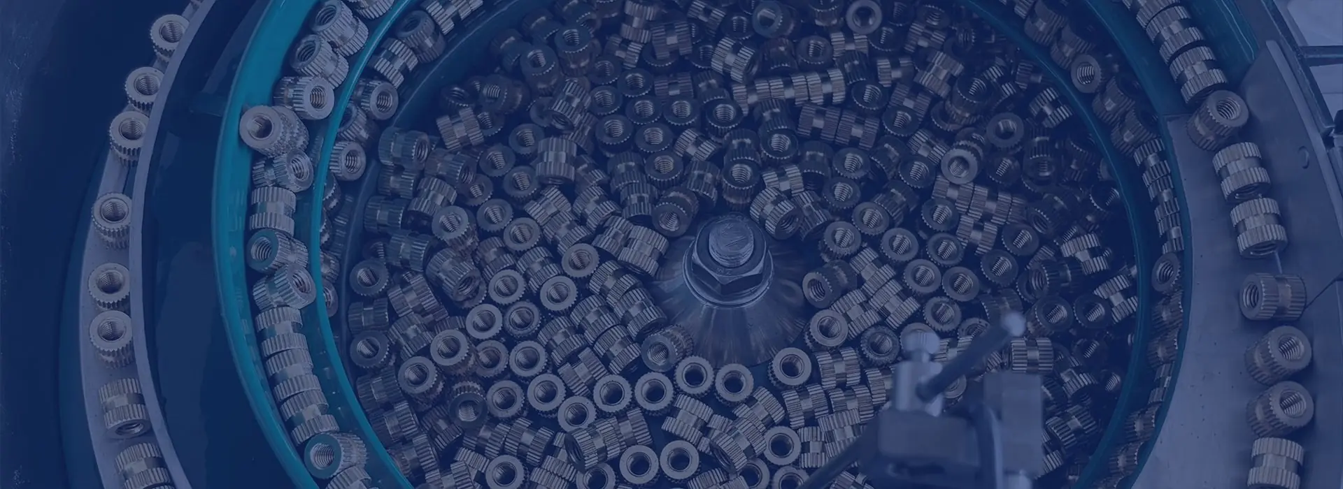
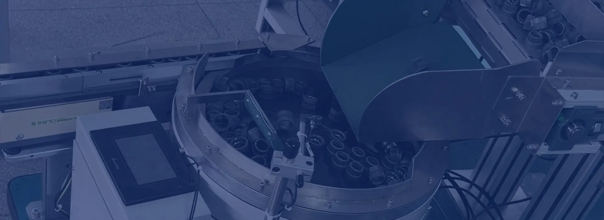
Component feeders—also called industrial parts feeders—separate loose components, establish or verify orientation, buffer flow and present one accepted part to an automated assembly, inspection or packaging process.
Sortation Solutions specifies the feeding principle, tooling, controls and interface as one application-engineered system.
What determines the right feeder? →Component feeder types
Geometry, handling risk, output condition and format range decide the technology—not a headline speed alone.
Application-engineered
Application-engineered
Application-engineered
Application-engineered
Application-engineered
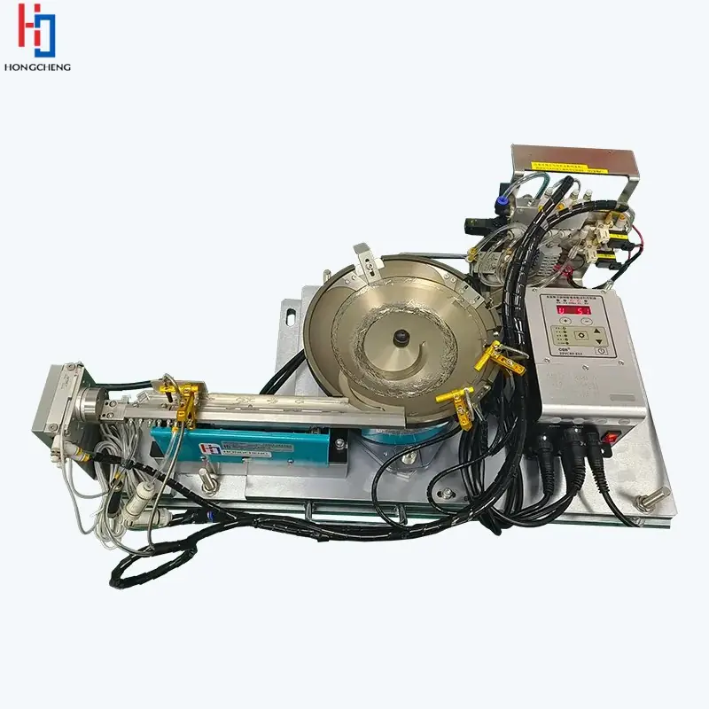
Application-engineered
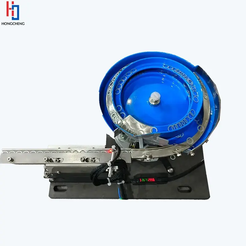
Start with the evidence
Two components with similar dimensions can behave completely differently in bulk. The selection review examines the real production condition.
Symmetry, centre of gravity, hooks, holes, flexibility and nesting.
Finish, marking risk, friction, oil, static and cleanability.
Accepted orientation, datum, pitch and sustained parts at hand-off.
Buffers, sensors, signals, guarding, access and fault recovery.
Manufacturing applications
From high-volume assembly parts to delicate or frequently changing products, the feed path is configured around production evidence.
Clips, retainers, electrical connectors, housings, seals, bushes, grommets and more.
Explore application ↗Contacts, terminals, connector bodies, pins, ferrules, inserts and more.
Explore application ↗Device components, caps, closures, small moulded parts and more.
Explore application ↗Screw caps, snap caps, dispensing closures, pumps, valves, fitments and more.
Explore application ↗Screws, bolts, nuts, captive nuts, washers, rings and more.
Explore application ↗Pressings, mouldings, inserts and production components across manufacturing.
Browse all applications ↗A measurable project path
Clear input evidence and agreed acceptance criteria reduce project risk at every stage.
Share parts, variants, orientation, target output and receiving-machine details.
Review bulk behaviour, handling risk and the complete feed path.
Test representative components against agreed acceptance criteria.
Engineer controls, buffering, safeguarding and the machine hand-off.
Confirm operation, training and documented evidence.
Buyer and engineering guides
Use practical, answer-first guidance to prepare a stronger brief, compare quotations and reduce integration risk.
Follow the complete path from loose parts to one controlled presentation.
Read the guide →Understand tooling, trials and the application data needed for a part-specific system.
Explore custom feeders →Plan hand-off, buffering, signals, guarding and acceptance with the next machine.
Open integration guide →Compare included scope and total ownership factors instead of headline price alone.
Read cost guide →Use an evidence-led sequence for jams, low output, marking and double feeds.
Troubleshoot a feeder →Get concise answers on selection, samples, rate, formats, trials and integration.
Browse all FAQs →Estimate downstream demand, design margin, gross presentation target, accumulation and trial count.
Use the planner →Start with the observed behaviour, then compare handling and trial routes without guesswork.
Diagnose the behaviour →Existing equipment support
Changed parts, worn surfaces, obsolete controls or a new machine interface do not always require a new feeding system. Start by separating a service issue from a tooling, component-variation or integration problem.
Straight answers
Final suitability and performance are confirmed against the actual part and agreed trial criteria.
The answer depends on geometry, centre of gravity, friction, tangling or nesting, surface sensitivity, required orientation, sustained rate and the downstream hand-off. Representative production samples are the safest basis for selection.
Specify sustained accepted parts at the agreed discharge condition over a stated test period, including normal replenishment and defined interventions. A short internal peak is not a reliable production measure.
Yes. The project can include mechanical interfaces, queue sensing, PLC or robot handshakes, buffer logic, guarding, reject handling and commissioning, subject to an application and controls review.
Send photographs or drawings, dimensions, material and finish, all expected variants, required orientation, target sustained output, available space and information about the machine receiving each part.
Start an application review
Share photographs or drawings, variants, material and finish, required orientation, target sustained output and details of the receiving machine.
A component feeder is a connected feed path. When output is low, separate the point where parts enter the feeder from the point where the receiving machine accepts them. That distinction helps identify which part of the system needs attention.
Observe whether the receiving feeder alternates between too few and too many parts. Record hopper level, replenishment requests and material still arriving after a stop request. More hopper capacity alone will not resolve bridging, uncontrolled overrun or a demand signal that does not reflect the feeder’s useful working level.
Compare the returned parts with the drawing and normal supplier variation. Look for nests, tangles, finish changes or an orientation feature that the proposed tooling cannot reliably distinguish. Keep rejected attitudes separate from damaged components. A rate counted inside the feeder can conceal poor usable delivery after orientation.
Review the final datum, spacing, escapement, pick confirmation and demand sequence. Establish whether a part is actually ready when the machine requests it, and whether a blocked downstream station stops replenishment appropriately. Trial recovery as well as normal demand. An accepted-part measurement at the real hand-off is more useful than comparing feeder speeds at different points.
Continue with Hoppers, linear feeders and controlled replenishment · Escapement and machine interfaces · Rate and buffer planning.
A fastener can leave a feeder in the right direction and still be unsuitable for insertion. Define the condition at the screwdriver, riveting tool or assembly fixture so feeding and fastening have a shared acceptance point.
Explore complete component feeding systems — read the detailed guide